Kasahara Laboratory, Department of Nuclear Engineering and Management, School of Engineering, The University of Tokyo

Failure modes of high temperature structures
Typical examples of failure modes of high temperature structures which are assumed to occur in usual operating conditions.
Development of consistent evaluation methods from load generation to failure for FBR vessel.
Clarification of damage mechanism from the thermal and mechanical load and understanding the range of uncertainty and the controlling factors of the complex heat-flow-structure interaction that occurs in nuclear reactors.
Design by Analysis concept for structural design standards
Framework for "Design by Analysis" and structural design criteria。
1.Failure modes assumption
Failure modes should be considered in the design phase. In the current design standards for LWR, it is assumed that the temperature range fluctuations never induced creep damage. For high temperature component, the thermal fatigue can induce creep damage and needs to be taken into account.
2.Damage mechanism clarification
For each failure mode, governing factors of the damage mechanism (stress, strain, etc..) and failure limit is deduced from strength theory.
3.Stress/strain calculated by elastic analysis
Stress and strain (elastic) analysis specifies the governing damage mechanism factors.
4.Setting stress/strain limits
Finally, design factors are created by combining the material strength from material data and the incidence and severity of the loads. These factors are used to set stress/strain limit.
※ASME Boiler and Pressure Vessel Code Sec.III, (1963)
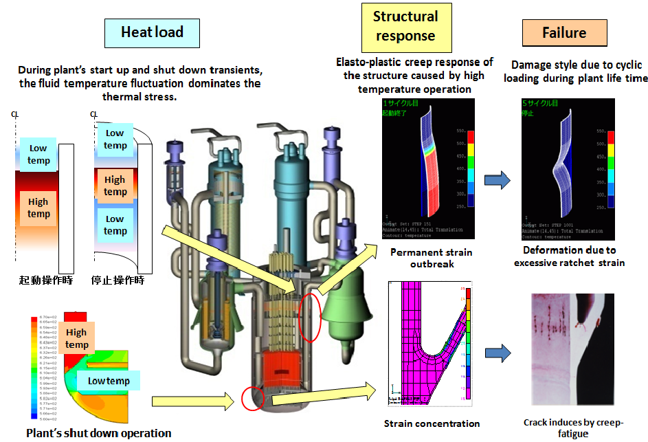
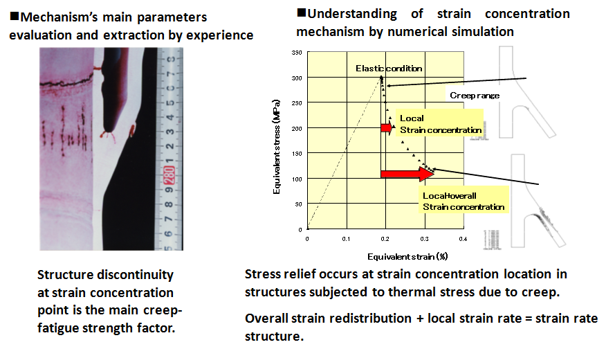
Strain concentration evaluation
FBR components operate at high temperature and low pressure. In these conditions high temperature creep is the dominant damage mechanism. Since the fatigue strength is reduced by creep strain rate due to inelastic behavior, stress redistribution appears and discontinuities in the structure are particularly important for correct damage prediction.
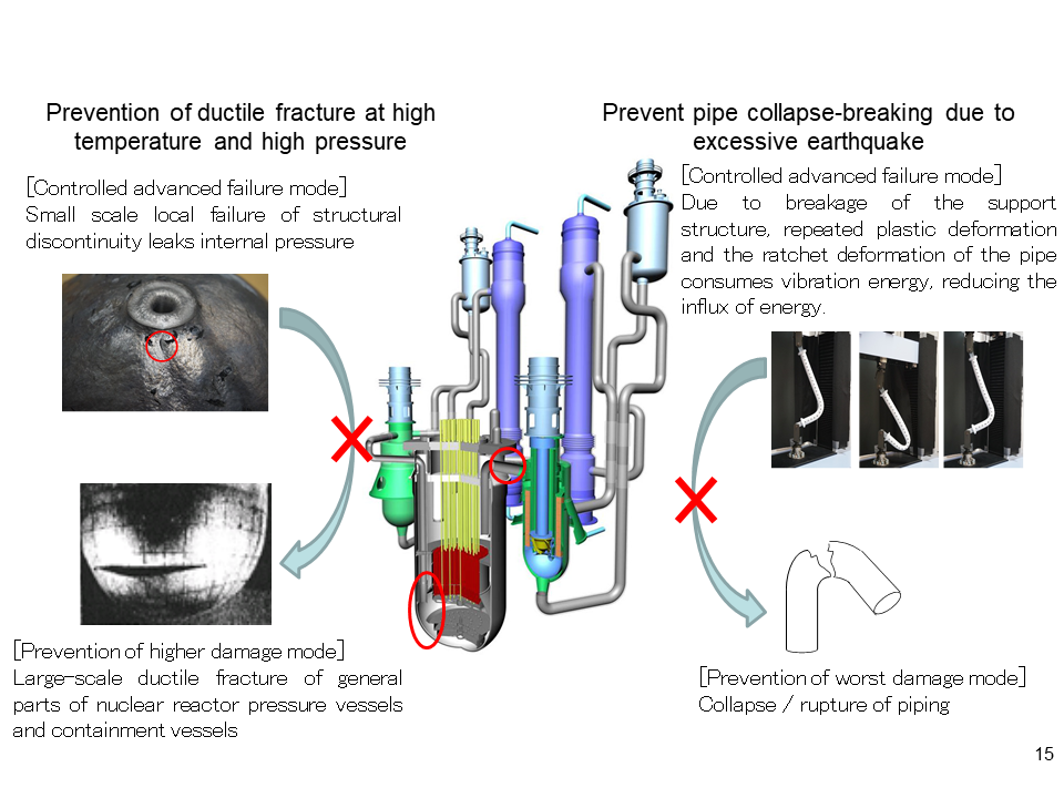
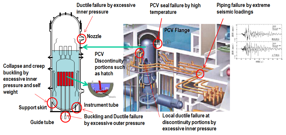
Clarification of the nature and damage mechanisms of the loads that exceeds design assumptions
Below are failure mode examples of pressure vessel, piping, and containment vessel when loads exceed design assumptions during severe accident or earthquakes.
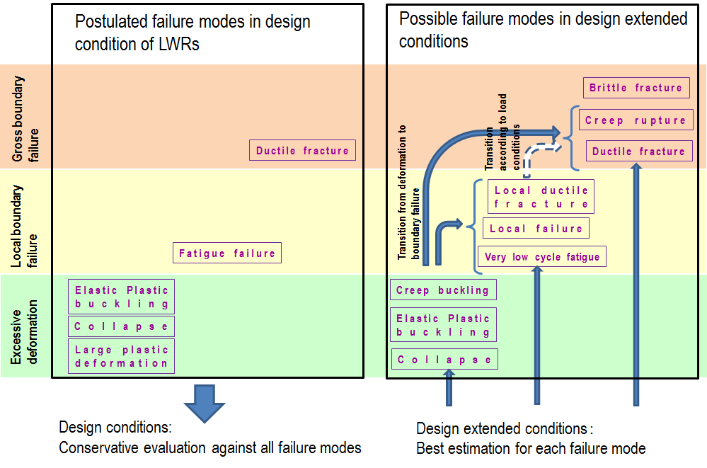
Organization of failure modes that abide design and that exceed design
Example of tensile strength test to check for overload by temperature and pressure
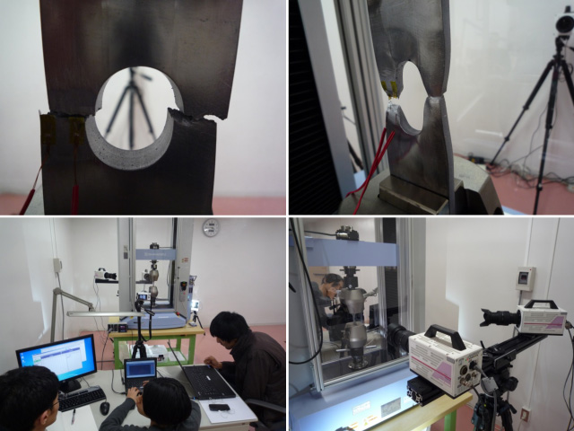
In comparison to tests with metal under normal conditions, tests with metal under elevated temperature conditions showed ductile fracture with large plastic deformation and necking.
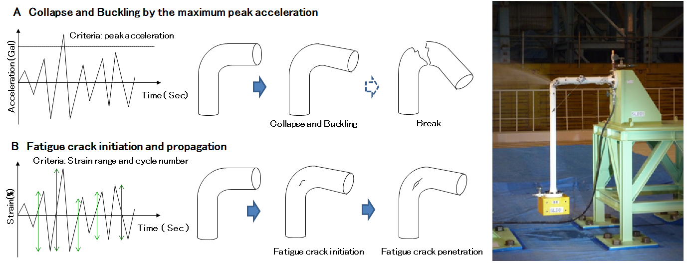
Vibration fracture experiment example to clarify the piping failure mode during earthquake
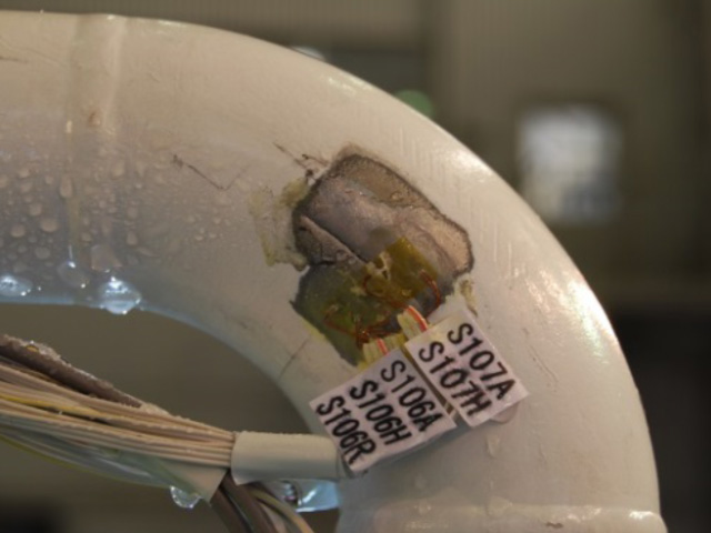
Piping failure modes under earthquake loading are shown in A and B
A shows the destructive test in both stainless steel and carbon steel, it has been found that pipe is destroyed by penetration as a result of fatigue cracks from the elbow flank in B.
A shows the destructive test in both stainless steel and carbon steel, it has been found that pipe is destroyed by penetration as a result of fatigue cracks from the elbow flank in B.
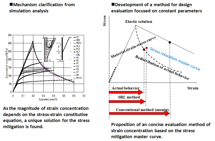
Development of analysis technology to concisely evaluate complex coupled phenomena such as elastic-plastic behavior due to creep deformation combined to non-linear heat flow.
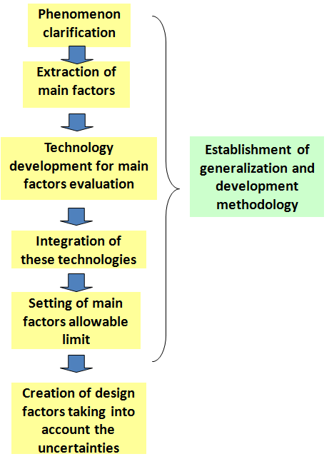
・Identify the main factors and criteria that govern the structural integrity.
・To develop technologies that focus on the element above to evaluate the structure response and strength to various loads.
・To include these technologies in the development of consistent strength response evaluation models.
・Acceptable damage limit is set based on the understanding of the major factor limit.
・The design factor is then set on risk analysis based on uncertainty of governing factors and frequency occurrence of loads.